Conventional and new-energy powertrains
Coordinate engine or electric-drive resources, battery limits and hybrid energy flows. Fuel-cell and electrified auxiliary-system controls are additional platform directions.
EQUIPMENT / PROJECT DEVELOPMENT
Modular control hardware for vehicle powertrains, body functions, network gateways, operator displays, diagnostics and autonomous-machine integration.
Configuration, availability and destination-market documentation are confirmed for each project.
TECHNICAL OVERVIEW
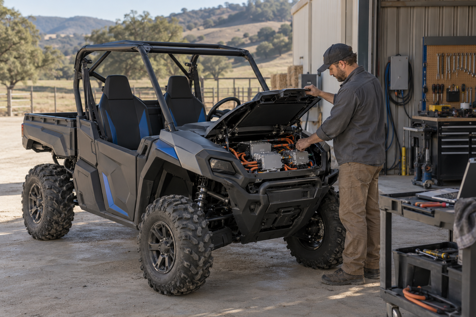
The architecture combines hardware resources, modular low-level software, a real-time operating system, middleware and application logic. A vehicle project defines the driver inputs, propulsion and energy-control behavior, auxiliary functions and communication interfaces on this platform.
Coordinate engine or electric-drive resources, battery limits and hybrid energy flows. Fuel-cell and electrified auxiliary-system controls are additional platform directions.
Connect vehicle data, telematics, gateway functions and a driving-domain controller. Autonomous operation also needs the chosen perception, localization, planning and by-wire actuation systems.
Adapt the hardware interfaces, network descriptions and vehicle logic to the application. Calibration, verification, production-line checks and service tooling follow the selected build.
TECHNICAL OVERVIEW
| Resource | 80-pin platform | 121-pin platform | 154-pin platform |
|---|---|---|---|
| Analog acquisition | 12-bit reference precision | 12-bit reference precision | 12-bit reference precision |
| Switch inputs | 16 channels; 0–36 V input | 24 channels; 0–36 V input | 33 channels; 0–36 V input |
| Frequency inputs | 2 channels | 4 channels | 4 channels |
| CAN interfaces | 3 | 6 | 6 |
| Output capability | High-side / low-side switching resources | High-side / low-side switching resources | High-side / low-side switching resources |
Platform resources are technical references. Pin allocation, channel electrical limits, supply requirements, switching-current ratings and firmware compatibility require the selected controller datasheet. The source output-channel descriptions contain overlapping labels, so exact output counts are not inferred here.
Interpret driving intent, coordinate propulsion demand and operating modes, and manage vehicle control states.
Coordinate energy optimization, system power-up/down, battery/charging control and electrified auxiliaries.
Monitor and display vehicle states, process faults, and coordinate CAN gateway and network management. Application logic can be adapted to the vehicle requirements.
TECHNICAL OVERVIEW
Reference functions include vehicle electrical management, door/window actuation, anti-pinch functions, central locking, wiper modes, washer control, lighting, horn and related body loads. The feature overview describes driving up to four window motors.
CAN communication, bootloader support and UDS diagnostics are listed. Diagnostic sessions, firmware compatibility, write access and operating-state restrictions are defined during integration.
A vehicle display can combine status pages with audio, navigation, communications and camera views. Screen size, display content, mirroring and multi-screen arrangements are customization options.
A combined acquisition/recording terminal is described with recording, video monitoring, storage and expandable camera inputs, including an example supporting five AHD camera channels. Recording retention and driver-identification functions are configured per project.
TECHNICAL OVERVIEW
Coordinates protocol conversion, data exchange and diagnostics between CAN segments and other vehicle networks. Topology, message routing, bandwidth, access control and network segmentation follow the vehicle architecture.
Collects position and vehicle data using J1939/CAN, cellular communications, satellite positioning and local flash storage. Periodic uploads, fault-code alerts, history queries and OTA support are described.
The diagnostic device reference includes Wi-Fi access-point operation, BLE 4.0 support for Android/iOS, an OBD-style 16-pin CAN connection and an 8–32 V input range.
End-of-line checks, permission-managed remote assistance, calibration and synchronized diagnostic records support engineering and service workflows. Vehicle-changing commands require controlled access and a defined safe service state.
TECHNICAL OVERVIEW
The reference includes an NVIDIA Xavier + TC387 + 88Q5050 hardware example and an alternative domestic-silicon architecture. Compute, interfaces, environmental qualification and supported software depend on the chosen variant.
Illustrative commercial-vehicle functions include electric power steering, an electronically controlled ten-airbag chassis, load-dependent fifth-axle lifting and following rear-wheel steering. These are separate chassis application examples, not standard UTV or mower equipment.
An unmanned mine-truck architecture combines vehicle control, network integration, remote monitoring and a managed operating area. Vehicle-specific steering/braking interfaces, perception, positioning and site validation remain necessary.
A component platform, automotive-grade chip or redundancy feature alone does not establish functional-safety certification or autonomous deployment readiness. Match the complete application, system behavior and verification evidence.
START WITH YOUR WORKLOAD
Tell us the task, terrain, operating schedule, quantity and delivery destination. We can review equipment configurations, electrical modules and supporting technical information together.
PROJECT / MODULE / COMPONENT
INTERACTIVE FUNCTIONAL MAP
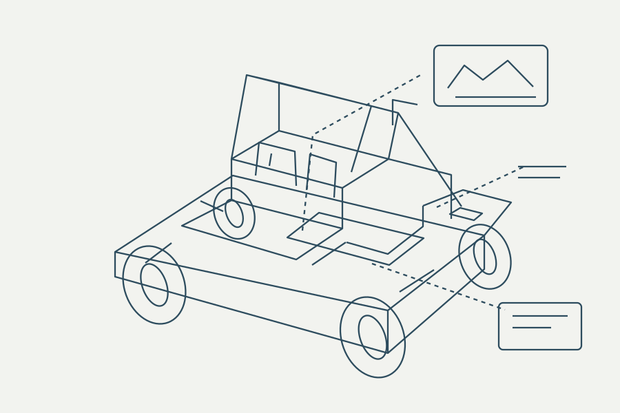
Select a numbered point or a module below. Locations are illustrative; the final installation drawing governs.