FUNCTIONAL MODULE / COMPONENT INTERFACES
Connections & moving cable
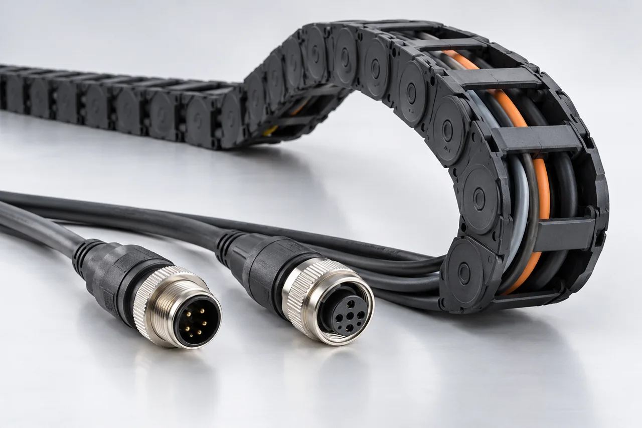
Power, signal and moving-cable installation must be defined as complete mating and routing arrangements.
FUNCTIONAL INTERFACE GUIDE
Functional breakdown
What makes up this module
M12 signal
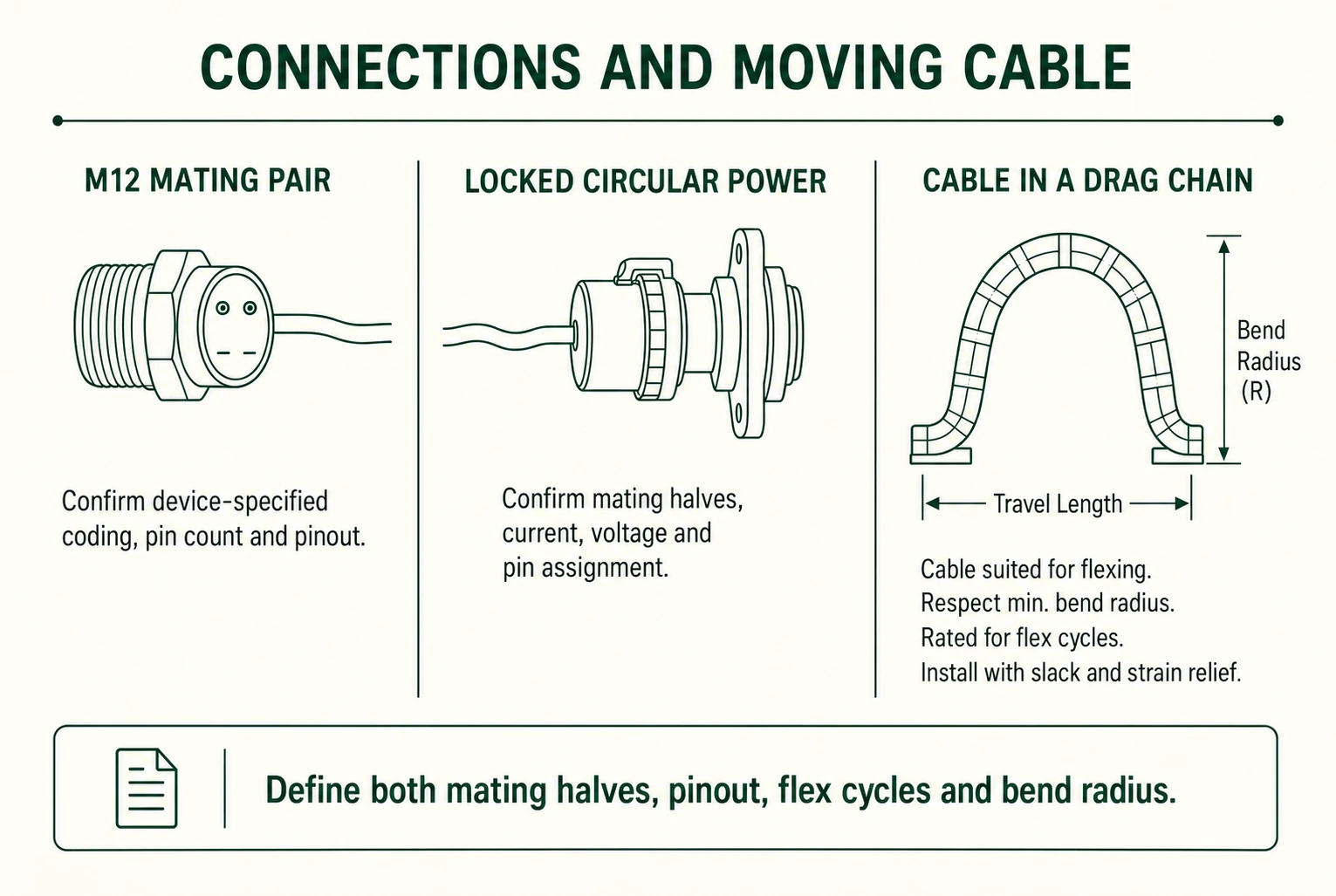
Confirm mating halves, device-specified coding, pin count, pinout and shielding.
Open component details ↗Locked circular power
Locked power mating pair: voltage, current, conductor size and who disconnects it during service.
Open component details ↗Cable and drag-chain duty
An installation condition: travel, minimum bend radius, flex cycles, shielding and strain relief.
Open component details ↗Define the module interfaces
01
Mating pair and pin assignment
02
Voltage/current and cable size
03
Flex, bend and strain relief
04
Washdown and service mating
PROJECT / MODULE / COMPONENT