FUNCTIONAL MODULE / SYSTEM CONTEXT — NOT QUOTED
Vision, navigation & sensing context
Review navigation, environment sensing and domain-control interfaces together with the associated vehicle and outdoor equipment project modules.
FUNCTIONAL INTERFACE GUIDE
Functional breakdown
What makes up this module
Payload power conversion
Input range must cover battery sag and charged voltage; define output, load peaks, isolation and heat dissipation.
Open component details ↗Device-specified connector interface
Confirm mating halves, device-specified coding, pin count, pinout and shielding.
Open component details ↗Moving-cable installation
An installation condition: travel, minimum bend radius, flex cycles, shielding and strain relief.
Open component details ↗Define the module interfaces
Payload supply and peak demand
Device-defined communication interface
Mounting and cable requirements
Equipment manufacturer’s system specification
System devices and associated project modules
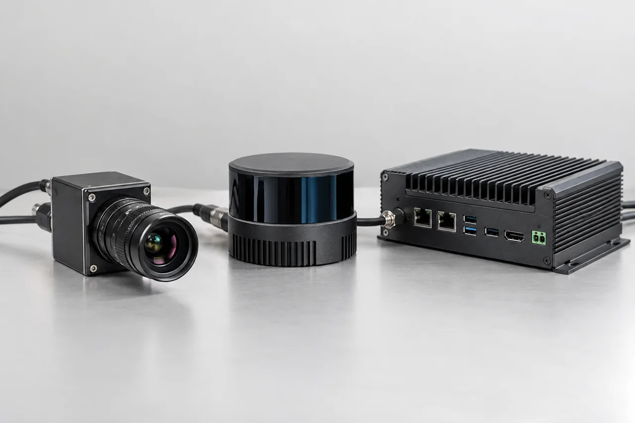
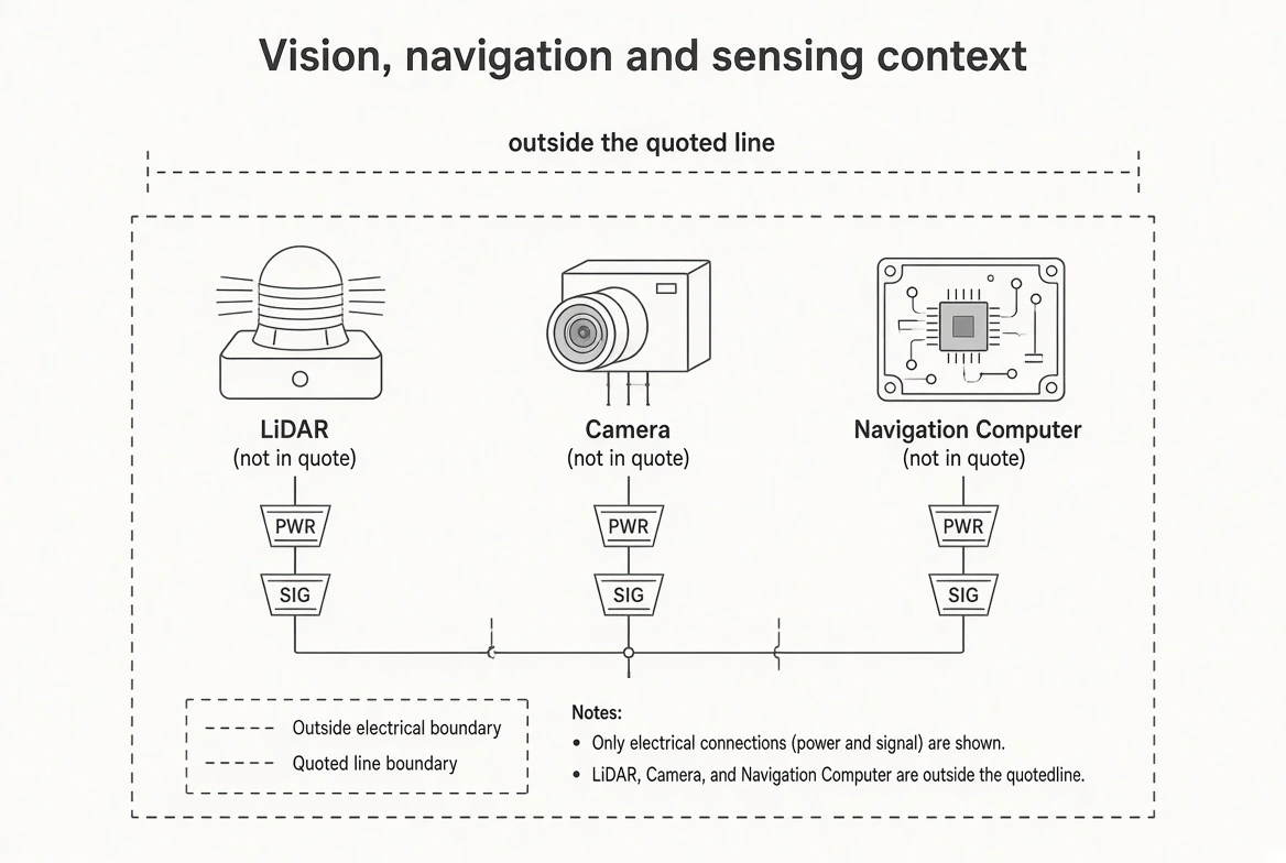
Vision: camera, lighting and processing. Navigation: localization sensors, navigation computer and software. Machine perception may also require LiDAR or safety scanners. These devices and their algorithms are not quoted here; the links above cover only related supply and connection interfaces.
PROJECT / MODULE / COMPONENT
Vehicle and outdoor equipment integration
Navigation & autonomous-machine integration
Localization, environment sensing, route planning and vehicle control.
Explore requirements & interfaces ↗Telematics & vehicle networks
CAN acquisition, gateway routing, location and cellular data transport.
Explore requirements & interfaces ↗Connected fleet & lifecycle services
Operations visibility, maintenance, engineering support and cloud deployment.
Explore requirements & interfaces ↗