Counts and frequency
Specify counts per revolution and the controller counting convention. Check maximum pulse frequency at operating speed.
MOTION / COMPONENT REQUIREMENTS
Provides incremental position or speed pulses. Position after power loss generally requires a reference procedure or separately retained position information.
Review the inputs ↓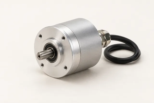
Specify counts per revolution and the controller counting convention. Check maximum pulse frequency at operating speed.
Provide supply voltage, line-driver or push-pull output, channel requirements and receiving controller input.
Confirm shaft or hub, mounting, coupling and cable arrangement. Match the controller interface rather than the motor brand.
An index is a reference pulse per revolution where provided. It is not an axis home switch and does not by itself identify machine position after power loss.
When position must be available after power loss, compare incremental referencing with an absolute-feedback arrangement supported by the controller. Check power-off movement, retention and required reference behavior.
Include the existing ordering code where available, operating duty, receiving interface, quantity and required delivery date. Selected model datasheets and drawings define ratings, mounting and connections.
Review the motion blocks ↗ Send a component requirement ↗RELATED COMPONENTS & FUNCTIONAL BLOCKS
Review these categories alongside the current component. A related category is not a verified compatible combination; selected model interfaces still need checking.
RELATED EQUIPMENT / PROJECT CONTEXT
Open an equipment configuration to see its component modules. These are application arrangements rather than stocked finished products.
PROJECT / MODULE / COMPONENT
Commercial tracked mowing, sweeping and grounds maintenance.
Explore requirements & interfaces ↗Farm/ranch UTV transport and field work.
Explore requirements & interfaces ↗Vehicle electronics, connectivity, diagnostic workflows and fleet services.
Explore requirements & interfaces ↗Driver intent, torque requests, energy coordination and defined actuator interfaces.
Explore requirements & interfaces ↗Pack energy, protection, state estimation and a charger matched to the site.
Explore requirements & interfaces ↗CAN acquisition, gateway routing, location and cellular data transport.
Explore requirements & interfaces ↗