M12 signal assemblies
A-coded assemblies may serve supported sensors or CANopen/DeviceNet interfaces. Coding alone does not establish compatibility: confirm the device-specific pin assignment and shield requirements.
INTERCONNECT
4 blocks. Review operating duty, receiving interface and supplier documentation before selection.
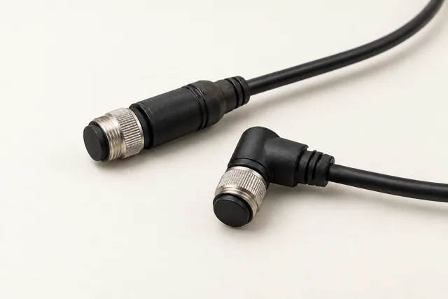
Both mating halves; pin count and device pinout; required coding and cable; operating exposure.
Requirements & interfaces ↗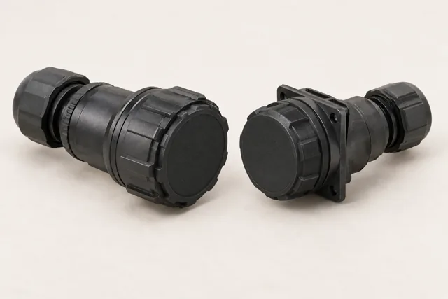
Operating voltage/current; locking and mating pair; field handling and mating cycles; washdown and cable requirements.
Requirements & interfaces ↗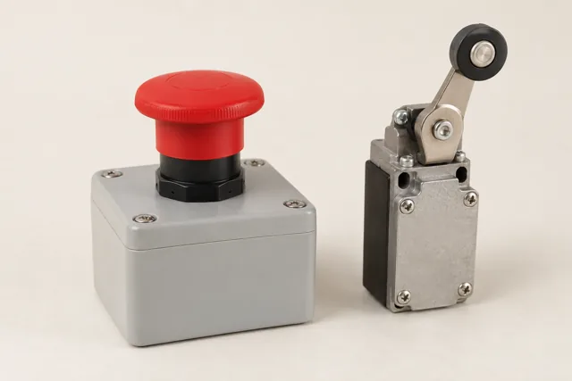
Receiving safety/enable interface; loop voltage and channels; monitoring requirements; reset and restart behavior.
Requirements & interfaces ↗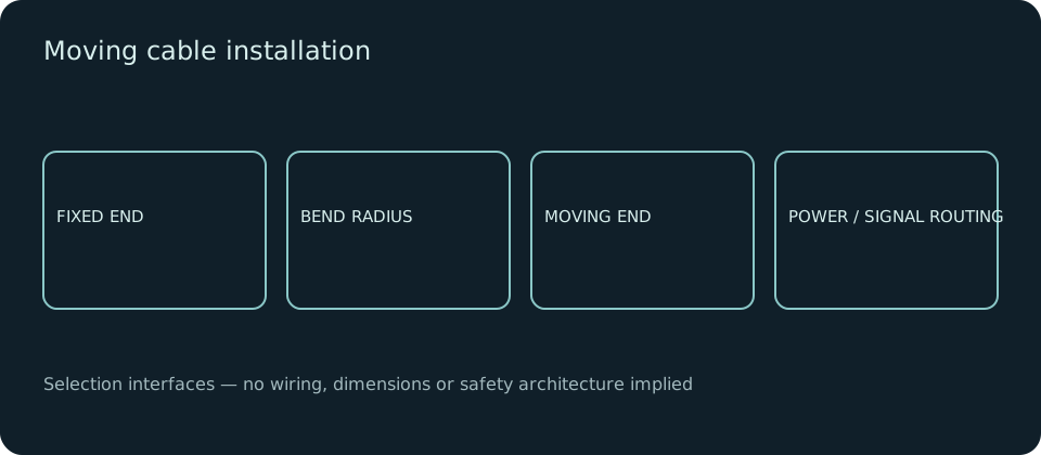
Flex cycles and travel; minimum bend radius; torsion where applicable; power/signal routing and exposure.
Requirements & interfaces ↗A-coded assemblies may serve supported sensors or CANopen/DeviceNet interfaces. Coding alone does not establish compatibility: confirm the device-specific pin assignment and shield requirements.
Specify whether live mating is required and permitted by the selected device. Do not infer an environmental rating from appearance.
An emergency stop is not a software flag or a generic series contact. The equipment risk assessment and selected controller documentation define the architecture, monitoring and required safety performance.
This is an installation condition, not another connector family. Select compatible continuous-flex cable and strain relief; confirm chain fill, separation and manufacturer limits.
SUPPLY SCOPE
Battery packs · BMS · chargers · LiDAR · safety scanners · cameras · navigation computers · fleet software.
Review battery/BMS, charging, navigation, camera interfaces and fleet services through the associated equipment and vehicle modules. Protective-system devices and vehicle-level validation are specified for the chosen installation; availability and compatibility are confirmed per project.