COMPONENTS / PROJECT DEVELOPMENT
Thermal management assembly
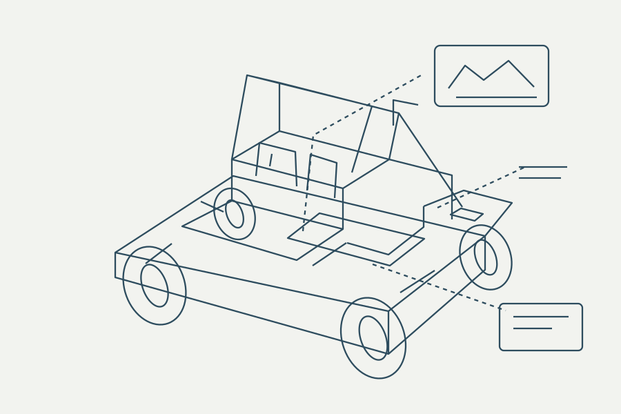
Coordinate battery, drive and cabin thermal loads through sensors, pumps, fans and control logic.
PROJECT / MODULE / COMPONENT
Function and reference configuration
Coordinate battery, drive and cabin thermal loads through sensors, pumps, fans and control logic.
The UTV architecture describes three thermal circuits: battery, motor and cabin. A selected build determines whether circuits use shared coolant, separate loops, air cooling or optional cabin conditioning.
PROJECT / MODULE / COMPONENT
Selection and integration inputs
- Heat rejection and ambient range
- pump/fan voltage/current
- flow and pressure
- sensors
- freeze protection
- startup strategy
- control outputs
- diagnostic thresholds and degraded operation.
PROJECT / MODULE / COMPONENT
Parent module
PROJECT / MODULE / COMPONENT
Related equipment projects
Outdoor automation
Commercial tracked mowing, sweeping and grounds maintenance.
Explore requirements & interfaces ↗Agriculture & field equipment
Farm/ranch UTV transport and field work.
Explore requirements & interfaces ↗Vehicle intelligence
Vehicle electronics, connectivity, diagnostic workflows and fleet services.
Explore requirements & interfaces ↗Start with the actual installation.
Send the equipment task, interface drawings, operating limits, quantity, destination and service requirements. Model selection, supply scope and verification documents are confirmed for the selected build.
Associated equipment and system pages
Vehicle control hardware
Review the vehicle architecture and installed controller interfaces.
Explore this equipment ↗New-energy UTV
Review farm and ranch vehicle integration requirements.
Explore this equipment ↗Commercial tracked mower
Review the energy, sensing or navigation requirements of the chosen mower configuration.
Explore this equipment ↗