MOTOR + TRANSMISSION
Planetary gearheads
Match the gearbox to both the motor interface and the driven load.
ENGINEERING DETAIL
Motor fit, ratio and output load
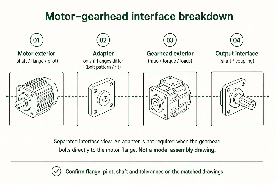
- Motor flange and input
- Pilot diameter, bolt pattern, flange dimensions, input shaft diameter/length and coupling arrangement.
- Reduction ratio
- Required motor speed and output speed define the ratio enquiry. Check maximum input speed and model-specific efficiency.
- Output torque and duty
- Provide continuous and peak output torque, acceleration, peak duration and duty. Check radial/axial loads and mounting orientation.
- Output interface
- Output shaft or flange, coupling/wheel connection, allowable backlash where relevant and installation space.
ENGINEERING DETAIL
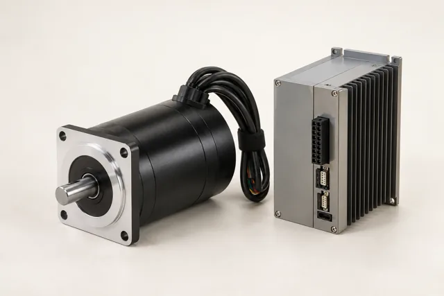
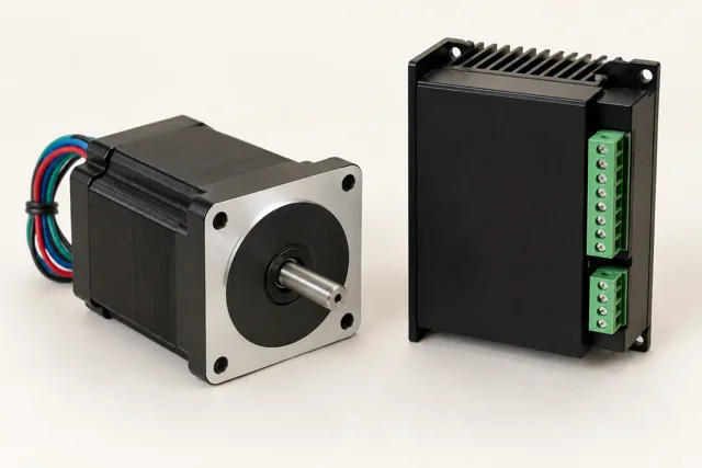
Read the complete pairing
TECHNICAL VISUAL GUIDE
Motor–gearhead interface breakdown
RELATED COMPONENTS & FUNCTIONAL BLOCKS
Complete the surrounding interfaces.
Review these categories alongside the current component. A related category is not a verified compatible combination; selected model interfaces still need checking.
RELATED EQUIPMENT / PROJECT CONTEXT
Where this component is considered.
Open an equipment configuration to see its component modules. These are application arrangements rather than stocked finished products.
PROJECT / MODULE / COMPONENT
Equipment projects and integration modules
Outdoor automation
Commercial tracked mowing, sweeping and grounds maintenance.
Explore requirements & interfaces ↗Agriculture & field equipment
Farm/ranch UTV transport and field work.
Explore requirements & interfaces ↗Vehicle intelligence
Vehicle electronics, connectivity, diagnostic workflows and fleet services.
Explore requirements & interfaces ↗Vehicle control & by-wire
Driver intent, torque requests, energy coordination and defined actuator interfaces.
Explore requirements & interfaces ↗Battery, BMS & charging
Pack energy, protection, state estimation and a charger matched to the site.
Explore requirements & interfaces ↗Telematics & vehicle networks
CAN acquisition, gateway routing, location and cellular data transport.
Explore requirements & interfaces ↗